TM1809 is a 9 output RGB LED drive IC , which means single IC can drive 3 RGB LEDs.This IC consists of data latch , signal reshape and high voltage driver circuits. It can be used for outdoor large-screen and color dot-matrix control applications.Since it can control 3 RGB LEDs at the same time ,this IC is useful when you want less components and more LEDs in your system.
How It Works
| TM1809 Internal block diagram |
Features of TM1803 IC
• CMOS Technology.
• Output voltage up to 24V .
• 256 Level Brightness adjustment circuit.
• Serial-shift and cascade Interface.
• Built-in RC oscillator. signal clock synchronization.
• Built-in power-on reset circuit.
• PWM control.
• Single line data Transmission.
• High speed and Low speed modes.
• 80mA maximum output current.
• Data transmission speed up to 800Kbps.
• Built-in Power stabilizer circuit.
• 3 RGB Output channels.
The Circuit Diagram
TM1803 Circuit Diagram 5v
 |
| TM1809 5v Circuit Diagram |
In this circuit , TM1809 IC powered by a 5v supply.Three common anode RGB LEDs being connected to the output pins of the TM1809 IC. The 104 (0.1uf) non-polarize capacitor work as a bypass capacitor to ground any AC components in the power rail , Two resistors (R2,R3) are connected at the data input and output pins to match the impedance (Optional) ,You can use a resistor between 100Ohm - 200Ohm.
TM1803 Circuit Diagram High voltage
 |
| TM1809 HV Circuit Diagram |
In this circuit diagram the supply voltage is grater than 5v (6v-24v). Since the three RGB LED's are connected to voltage over 5v ,voltage divider resistors (R1,R4,R5,R6,R7,R8,R9,R10,R11) in series with the LED pins being used.The value of these resistors can be calculated using the equation.
Rled = VRled / Iled
Rled in this case the resistor value .Iled is the current flow through the LED. VRled In this case Voltage drop between resistor pins which is [ Vs - Vled ] (Vled means
the voltage drop between LED's anode and cathode). These values can be
measured using a multi-meter or referring the datasheets of the RGB
LED.As you can see in the diagram , you can use multiple LEDs in series
with TM1803 pixel LED IC.
In order to protect the IC from
higher supply voltages a resistor (R12)
in
series with the (VDD) pin is being used .The value of that resistor can
be calculated using the below equation .( If your power supply is 5v This
resistor is not necessary).
R1 = VR1 / I
Where "VR1" is [ Vs (supply voltage) - 5v ] and "I" equals 1mA . eg - If the supply voltage is 6v the R12 value should be 1Kohm , if the supply voltage is 9v the R12 value should be 4Kohm .Here is a list of resistor values for different supply voltage levels.
 |
| TM1809 resistor values |
Designing Pixel LED PCB
 |
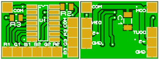
| TM1809 PCB 5V |
• U1 - TM1809 IC (SOP14)
• R2 ,R3 - 0.1 W (8050)
• C1 - 0.1uf (Ceramic Non-polarized Capacitor 1206 )
This is a 18mm x 13.5mm PCB designed only using SMD components. IC package is SOP14 .The resisters (R2,R3) are 0.1 watt 8050 package. SMD pads are being used for the input , output and RGB LED connections."COM" pad is where the common pin of the RGB LED should be soldered .Use the Gerber files if you wants the PCB to be manufactured by a PCB manufacturer like JLPCB.
[ Download the Proteus Project and Gerber Files ]
How to use the TM1809 Pixel LED Unit
| TM1809 Pixel LED Wiring Diagram |
As you can see in the diagram each TM1809 pixel led unit soldered with three RGB LED's .The pixel LED controller connects to the first pixel LED unit , Data terminal of the controller connects to the Data IN of the first pixel led unit.The 5v and ground of the controller connects to the +5v and GND of the first pixel LED unit respectively.
DOUT of the first pixel LED unit connects to the DIN of the next pixel LED unit.The 5v and GND of the first pixel LED unit connects to the +5v and GND of the next pixel LED unit respectively.Like wise each pixel LED unit connects in series .The number of the units only limited by the pixel LED controller capabilities.


No comments:
Post a Comment