WS2821 is a 3 channel constant current output RGB LED drive IC,which adopts two wire communication. WS2821 have power supply voltage stabilizing circuit, time base circuit, a signal decoder block, data buffer and built-in address storage circuit.WS2821 have three independent output driven channels, These each individual pin operate at constant current about 19mA, which also can be set using a resistor up to 60mA maximum current.
How it Works
This IC uses two line DMX512 communication method to communication. The two lines it uses to communicate is data line and address line .In this case the data line is common which means every IC in the pixel LED network receives the data from the controller at the same time.First WS2821 receives address data from the controller and it checks if the address received by the chip matches the address of the IC , If it matches IC sends acknowledgement signal to the controller then it receives the data from the controller .If it doesn't mach . it pass the address data to the next IC in the network. The PWM signal of each out pin will be set according to the received data.
DMX Addressing
Since this IC uses DMX512 protocol, each IC in the network needs a unique address to receive corresponding data . The fist thing we need to do is setting the address of each chip in the network .This address of the IC is between 0 -512 which can be programed using the Pixel led controller or DMX decoder . There are few ways to program the DMX address of the IC .
• Manual DMX Addressing - In manual DMX addressing you can setup pixel led units DMX address using the pixel LED controller's DIP switches .
• Automatic DMX Addressing - In automatic DMX addressing the pixel led network is connected to the pixel led controller . When automatic DMX addressing is activated in the controller each pixel LED unit's addresses will be programmed in ascending order . The first pixel LED unit will be programmed with the address 0 and the next one will get the address 1 likewise the controller will program each pixel LED in the network automatically.
• Software DMX Addressing - In Software DMX addressing the software like LEDEdit can be used for DMX addressing . Benefit of this method is that you can set some settings such as starting channel , channel spacing and end channel .
Features of WS2821 IC
• Signal can compatible and expand the DMX512(1990) protocol signal.
• Data transmission speed up to 750Kbps.
• The built-in voltage regulator.
• Output voltage can bear up to 24V
• PWM R/G/B out puts.
• 256 adjustable gray levels.
• R/G/B output up to 60mA (default current 19mA).
• Network can connected up to 1024 units.Circuit Diagram of WS2821
WS2821A Circuit Diagram
 |
WS2821A Circuit Diagram
|
In this circuit diagram WS2821A package is being used with a common anode RGB LED .The 5v supply which gives constant current output about 18.5mA at each output pin , the advantage of this is that the pixel LED can retain it's luminescence and color temperature due to constant current drain through output pins of the IC. In order to reduce the effects of power noise and a current limiter a 100ohm(R4) resistor in series with the (VCC) pin being used .The 104(0.1uf) non-polarize capacitor work as a bypass capacitor to ground any AC components in the power rail , Three 33ohm resistors are connected at the data input , address input and address output pins to match the impedance (Optional).
WS2821A 12v Circuit Diagram
 |
WS2821A 12V circuit Diagram
|
As
you can see in the circuit diagram three RGB LED's being used with the
WS2821A pixel LED drive IC.At the VCC pin of the IC 2.2Kohm resistor is
being used to reduce the voltage to the IC .The R6 at OUT R pin is a voltage divider The value of that resister can be
measured by using the V= I x R equation. In this case R = V/ I . V in
this case voltage across the R resister which can be measured by Vs -
Vled (supply voltage - Voltage across the R LED ,which can be measured
using a multi meter ) .Since "I" is constant at 18.5mA, Finally we can
come to a equation [ R = Vs -Vled / 18.5mA]
WS2821B Circuit Diagram
 |
WS2821B Circuit Diagram
|
In
this circuit diagram WS2821B package is being used with a common anode
RGB LED .The 5v supply which gives constant current output
at each output pin.This IC version have some additional pins such as REXT and SPWM . You can set the output current by grounding the REXT pin VIA a resistor(R4) .This resistor value can be calculated using this equation.
Iout (mA) = [15xVref] + Vref / Rext x 3 x 10⁴
Vref = 1.24v.Without the Rext(R4) resistor the current output will be 18.5mA . In order to reduce the effects of
power noise and a current limiter a 100ohm(R4) resistor in series with
the (VCC) pin being used .The 104(0.1uf) non-polarize capacitor work as a
bypass capacitor to ground any AC components in the power rail , Three
33ohm resistors are connected at the data input , address input and
address output pins to match the impedance (Optional).
WS2821B 12v Circuit Diagram
 |
| WS2821B 12V circuit Diagram |
As
you can see in the circuit diagram three RGB LED's being used with the
WS2821B pixel LED drive IC.At the VCC pin of the IC 2.2Kohm resistor is
being used to reduce the voltage to the IC .The R6 at OUT R pin is a voltage divider The value of that resister can be
measured by using the V= I x R equation. In this case R = V/ I . V in
this case voltage across the R resister which can be measured by Vs -
Vled (supply voltage - Voltage across the R leds which can be measured
using a multi meter ) .Since "I" is set by the Rext resistor , Finally we can
come to a equation [ R = Vs -Vled / Iout]
Designing WS2821A PCB
WS2821A SMD PCB 5v I
 |
WS2811A Pixel LED PCB 5V
|
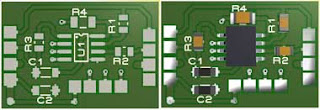
• U2 - WS2811 IC (SOP8)
• R1 , R2 ,R3 - 100Ohm(1206) , 33 Ohm (0805),33Ohm(0805)
• C1 ,C2 - 0.1uf (1206)
This is a 25mmx18mm (WxH) double side PCB.To save the space this PCB designed with only using SMD components.The IC package in this case is SOP8. C1 and C2 are ceramic SMD (1206 package) .R1 ,R2 and R3 are 0.1 watt (0805 Package) resistors. R4 is a 0.125watt (1206 Package) resistor.Instead of through hole header ports SMD pads being used for the input , output and for the RGB led connectors. Use the Gerber files if you wants the PCB to be manufactured by a PCB manufacturer.
WS2821A SMD PCB 5v II
 |
| WS2821A SMD PCB 5v |
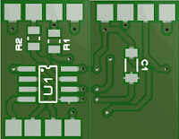
This is a 2 layer PCB. Designed to absolute minimum dimensions and minimum components .
It's a 11mm x 17.5mm PCB designed only using SMD components .The WS2821A IC
package used is SOP8 . SMD pads are being used for the input , output and RGB LED
connections.Use the Grabber files if you wants the PCB to be
manufactured by a PCB manufacturer.
[ Download the Proteus Project and Gerber Files ]
Designing WS2821B PCB
 |
WS2821B Pixel LED PCB 5V
|
• U2 - WS2811 IC (SOP14)
• R1 , R2 ,R3 ,R5 - 100Ohm(1206) , 33 Ohm (0805),33Ohm(0805) , xxOhm(0805)
• C1 ,C2 - 0.1uf (1206)
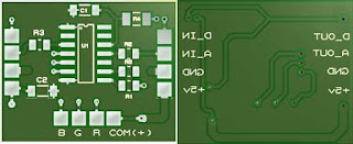
This
is a 25mmx20mm (WxH) double side PCB.This PCB designed only using SMD components.The IC package in this case is
SOP14. C1 and C2 are ceramic SMD (1206 package) .R1 ,R2 and R3 are 0.1
watt (0805 Package) resistors. R4 is a 0.125watt (1206 Package)
resistor.R5 is the Rext resistor as I have mentioned in the diagram section the value can be calculated using the given formula ,If you are OK with 18.5mA output don't solder this resistor .Through hole header ports have been replaced with SMD pads. Use the Gerber files if you wants the PCB to be manufactured by a PCB manufacturer.
[ Download the Proteus Project and Gerber Files ]
How to use WS2821 Pixel LED Unit
 |
WS2821 pixel LED wiring diagram
|
In this wiring diagram each WS2821 unit connected in series.The first pixel LED unit connects to the controller .The
controller's DMX+ terminal connected to the data IN of the pixel LED
unit and the DMX- terminal connected to the Address IN of the pixel led unit . The GND and the +5 terminals of the controller connects to the
GND and the +5 pad of the pixel
LED unit respectively.
At the other end , The data OUT pad of the 1st
pixel LED unit connects to the data IN of the next pixel LED unit and the address OUT connects to the next pixel LED unit's address IN pad.The
GND and +5 pads of the pixel LED unit connects to the GND and +5 pads of the next unit respectively.You can connect up to 512 units per pixel LED port .
Some pixel LED controllers doesn't have DMX+ and DMX- terminals, instead they uses terminal A and terminal B as DMX+ and DMX- . If the system doesn't work after wiring, swap the first pixel LED controller's data in and address in wires that connects to the DMX+ and DMX- of the pixel LED controller .Since different manufactures uses diffrent terminal configuration please refer to the user manual of the controller to find the correct terminals for DMX+ and DMX -.


No comments:
Post a Comment