Controller Manual Operation
This is a simple project I did last year .Friend of mine asked me to create it for him ,His request was to create a simple alarm that trigger when the maximum water level reached but I decided to create a automatically controlled water pump system simply using hall effect sensors .
Function
The function of the system is to turn off the pump when the Maximum water level is reached and turn on the pump when the pump when the minimum water level is reached .
Hall effect sensors
 |
| Hall Effect Sensors |
Controller
 |
| Inside Wiring |
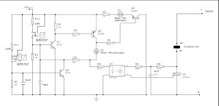
The controller consists of two latch circuits and a Triac switch .function is to set the latch when minimum level hall sensor triggered and reset it when the maximum level hall sensor is triggered .The latch output will control the Triac switch which will cause the contactor coil to energize ,ultimately controlling the pump .
Power supply
Contractor
Features
 |
| Manual and Automatic Switch |
- Low operating power .
- Indicators .
Controller Circuit Diagram
 | |
| Water pump controller Circuit Diagram |
Final Product
I used Telephone wires to connect hall effect sensors to the controller.The hall effect sensors are placed inside the pipe correctly placed on required levels. The 1/2 inch Pipe placed inside the tank .The pipe goes through a Donut type Magnet which is placed inside a floating rigifoam ball (Which are used in fishing). This will cause magnet to float with the water level .
 |
Sensor placement
 |
| Sensor Placement - Water pump controller |
The Hall effect sensors are placed inside a PVC pipe ( Ф 1/2 inch ) .The minimum level sensor at the bottom of the pipe and the maximum level sensor at the top of the pipe ,Use some rubber vine bottle stopper at the top of the pipe to secure the wires of the sensors so they won't move .Use a pipe endcap at the bottom to seal the pipe to water seal it . For the floater I used a rigifroam balls that used in fishing and place a donut magnet ( scrapped from a speaker ) in the bottom in order to align the ball with the pipe please use another non magnetic donut shaped object at the top .


