| T-1000AC Pixel LED Controller Tutorial |
T1000AC Pixel LED Controller is a special Pixel LED controller designed to powered by the AC outlet instead of a DC power supply or adapter . You can directly connect this controller to your house AC outlet. This controller can be connected to a AC outlet which have voltage between 110 - 240 VAC . T1000AC is actually T1000S controller with inbuilt power supply for the controller .Yes ,You are still require external Power supplies for the Pixel LEDs .
Converting to 110VAC
If your country or local area house power grid is 110V .Try to power it using 110VAC , If it is working fine you can skip this part of the tutorial ,But if it doesn't you have to convert the 110V to 220 or you have to replace the transformer inside the controller. If you supplied below 110 VAC to the primary of the existing transformer which is designed to step-down 220VAC to 12VAC , The output will be nearly 5.5VAC after full bridge rectification it will be around 4.5VDC which is not enough for the [L2596-5.0 regulator] IC .,The regulator voltage range is 7.5 V to 40 V .
Using Step-up Transformer
 |
| 110VAC to 220VAC Step-up Transformer |
You have to use a step up Transformer of 1:2 ( Primary : Secondary ) coil ratio .which will convert the 110 ACV to 220VAC Or you can use a 110v to 230 converter available in the market . The current ratings should be at-least 2.5A .
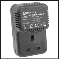 |
| 110v to 230 converter |
| T-1000AC Pixel LED Controller inside |
If you don't like extra components hanging outside you can replace the internal transformer so you can directly plug your controller to a 110v outlet . De-solder the wires of the existing transformer from the main board (please take a photo of the arrangement before de-soldering )and replace that transformer with 110VAC to 12VAC step-down Transformer . Solder the new transformer input and output wires to the main board ( please refer to the photo that you had taken before de-soldering .)
T-1000AC Specifications
*. Input voltage : 220 - 240 VAC
*. Power : 2W
*. MAX programs : 16
*. Program method : Off-line(SD Card)
*. Maximum pixel LEDs : 2048
*. Working temperature: -30 ° C - 85 ° C
*. Working voltage: AC110-AC220V
*. Weight: 735g
*. Size: 182 * 99 * 52mm
*. Power : 2W
*. MAX programs : 16
*. Program method : Off-line(SD Card)
*. Maximum pixel LEDs : 2048
*. Working temperature: -30 ° C - 85 ° C
*. Working voltage: AC110-AC220V
*. Weight: 735g
*. Size: 182 * 99 * 52mm
T-1000AC features
*. Supports 32—256 Gray level software Gamma correction.
*. Support the rules and special-shaped handle.
*. Single-port output,can support 2048 pixels.
*. Off-line (SD Card) control.
*. T-1000AC can store a maximum of 16 programs.
*. Compatible with single line or double line chips.
One of the most impotent features of this controller is that it has 128MB internal flash memory so you can copy the programs of the SD card into the internal flash memory and run the controller without the SD card .You can either use the SD card or internal memory.
One of the most impotent features of this controller is that it has 128MB internal flash memory so you can copy the programs of the SD card into the internal flash memory and run the controller without the SD card .You can either use the SD card or internal memory.
Note that one of the main different between T1000Sand T1000AC is T1000AC doesn't support RS485 based LED drive chips . But you might be able to use something like [THIS] to convert SPI signal to RS485 .
Note : Above features may or may not available in your product due to different manufactures may remove some features to produce it cheaper . Please ask your seller before you purchase.
TM1803,TM1804,TM1809,TM1812,TM1829,TM1903, TM1909,TM1912
UCS2903,UCS2909,UCS2912, UCS1886,UCS6803
WS2811,WS2801,WS2803
INK1003,INK1003
SM1671,SM16716,SM16726
LPD8806,LPD1882,LPD6812,LPD6813
P9813
LX2003,LX2006
DMX512
TLS3001,TLS3008
Note : Above features may or may not available in your product due to different manufactures may remove some features to produce it cheaper . Please ask your seller before you purchase.
Supported Pixel LED Drive Chips
TM1803,TM1804,TM1809,TM1812,TM1829,TM1903, TM1909,TM1912
UCS2903,UCS2909,UCS2912, UCS1886,UCS6803
WS2811,WS2801,WS2803
INK1003,INK1003
SM1671,SM16716,SM16726
LPD8806,LPD1882,LPD6812,LPD6813
P9813
LX2003,LX2006
DMX512
TLS3001,TLS3008
Components Of The Controller
| T1000AC controller inside |
A - SD card slot .
B - 4 digit Seven segment Display .
C - Button Speed +
D - Button Speed -
E - Button playback mode Selection ( Auto/Manual )
F - Button Drive IC Selector .
G - SPI Clock Out.
H - SPI Data Out.
I - Data Ground.
J - AC connector ( Female ).
Seven Segment Display - Is used to display the playback speed , Auto / Manual ,Errors and Drive chip name .
Speed Buttons - Speed + is to increase the playback speed and Speed - is to decrease the playback speed . Speed can be changed between S00 to S99 and will be displayed when you change it .
Playback Mode Button - Is used to change the playback mode .There are two Auto and Manual .In auto mode each pattern files will be repeatedly played one after another ( Display will show A-01 when this mode is activated ) .In Manual mode the selected pattern file will be played repeatedly (Display will show C-xx (xx is the file number) ).
Drive IC Selector - The controller per-programmed with drive chip communication methods . When boot up you can press this button and choose the corresponding drive chip model that you are about to drive .
Data Port - Which is used to connect the Pixel LED String/Strip .Supports both single line communication (Data only) drive chip models and dual line ( Data and Clock) communication drive chip models. Ground is the data ground connected to the ground of the LED Strip/String .
Wiring The Pixel LEDs
As I said before you can drive both single line communication (also known as 3 wire communication method ) drive chip models and dual line ( also known as 4 wire communication method ) communication drive chip models . Single line communication LED strips/strings have three wires (Gnd , Data , Vcc) and dual line strips/strings have 4 wires (Gnd , Data ,Clock , Vcc) .Here is how you can wire the system . Here is how it can be wired
3 Wire Connection
In this method we use external power supply to supply the voltage to the Pixel LED strip or string and the ground of the controller (data ground) and power supply ground (- ) is connected together (Common ground) .The data line of the controller is connected to the data line of the LED Strip/string . Here is the common color code and connection table of the Pixel LED String .
4 Wire Connection
3 Wire Connection
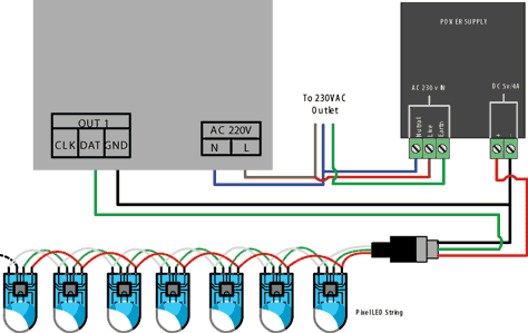 |
| T1000AC Pixel LED Controller wiring - Method 01 |
In this method we use external power supply to supply the voltage to the Pixel LED strip or string and the ground of the controller (data ground) and power supply ground (- ) is connected together (Common ground) .The data line of the controller is connected to the data line of the LED Strip/string . Here is the common color code and connection table of the Pixel LED String .
| T1000AC Pixel LED Controller connection table 01 |
4 Wire Connection
 |
| T-1000AC wiring Diagram 4wire |
| T1000AC Pixel LED Controller connection table 02 |
Connection between each String/Strip
| Connection Between each String/Strip |
Since the LED strings / strips are comes in 150 LED's per LED string / strip ,In order to increase the amount of LEDs you have to connect each strings together in parallel ,For that reason each one of LED strings have connectors on both sides (Female and Male ) and also each strings first LED have extra VCC (red wire) and GND (White/Blue) wire coming out of it .So every LED String need to be connected to the Power supply using that extra wires that coming out of the first LED.If not the LED string will stats to dim due to lack of current .Which means the wire diameter of a string is only enough to carry current require for a one string .Make sure that you use a wire with enough diameter to carry the amount of current required by the string/strings when you are wiring them to the power supply .
Software
T1000AC Pixel LED Controller can be programmed using LED Edit 2012 version Click to Download LED Edit 2012.
Selecting the Controller in the Software
Note that there is no T1000AC listed as a controller in the new project window . But don't worry! , Here is how to do it .When you are selecting the controller from the list please follow this method .
You have to select the controller type as T-1000 instead of T-1000AC .
Controller Name in the list = Controller Name + Drive chip Name
Eg- If your controller name is T-1000AC and Drive chip name is WS2811, You should select T-1000-WS2811 from the list .
Problem - Error on seven segment display , No display
This is may due to few reasons -
*. Controller cant detect the SD card - Damaged SD card,Unsupported SD card ,Unsupported file format.
fix - Check whether the SD cad is supported type (128,256,512,1GB,2GB SD card) ,Insert it to the card reader and format it using the windows format tool as I mentioned previously in this tutorial .replace the files again and try again .
*. Oxidized card pins or controller pins - remove the card and check the gold plating of the pins if they where damaged and gold plate was gone replace the card .If the controller port is damaged got gold plate was gone you have to replace the port .
*. Unknown file type or no file - The file type should be ".led" other file types may cause error light to flash.please recheck the files using a PC .
*. Different controller Type selection - If you have selected T-1000B-XXXX instead of T-1000-XXXX it will cause an error .
If you are using internal flash memory -
*. The flash memory is empty or copying files from SD card to flash memory failed .
*. damaged flash memory Chip .
No error Display but no LED effect either
This is due to physical error - Damage wires in the LED String or Damaged or oxidized port or connectors or due to selecting wrong drive chip type in the new project window check the "Selecting the Controller in the Software " section at the top of this article. If ports are damaged then you have to re solder them .If connectors are oxidized you have to use NC-Tinner to clean them you can use a used tooth brush and dip it in NC Tinner and brush the oxidized parts of the controller and the LED String or use a contact cleaner spay .
limit the amount of time you insert and remove the SD card to the controller , Because every time you doing this will cause the gold plated pins to scratch which will lead to oxidizing of the pins .
Environmental conditions may cause damage to your led string and the LED controller ,The controllers are not designed for out-door use, It's for indoor use only .If you are putting the LED string out-door please make sure to use the water sealed LED strings. But even the water sealed led strings may damage due to hash environmental conditions .
Power Supply
Please read my article on selecting the Power supply for your Pixel LED project for more info
SD Card
 | |
|
SD cards are used for offline controllers because they don't have a internal memory to store the program files .you have to connect your SD card to your PC VIA card reader and save your program files in the SD card .There are many types of SD cards available today (SD,MiniSD,Micro SD ). You can use any one of these cards with your controller but they are different in sizes and also pin-outs are different too. So first you need to find the type of the SD card that your controller supports and use that type of SD card (T-1000S controller supports "SD" type SD cards )or you can use a adapter of that card and insert your card inside that adapter .
eg-If you have micoSD (TF) card and your controller supports "SD" types ,You can use Micro SD to SD adapter .
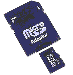 |
| Micro SD to SD adapter |
There also mini SD to SD adapters and SD to mini SD adapters .
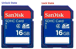
Most controllers supports SD card type .Make sure that the card lock switch is not in the lock state .
Type and size of the SD card
If your controller don't support SDHC type SD cards try a normal SD cad .There is no physical difference between them but SD cards memory is equal or less than 4GB and SDHC cards capable of memory more than 4GB.
Capacity
Capacity
For The T-1000AC Controller ,The recommended capacity is between 128MB - 4GB ,Which means you can use 128MB , 256MB, 512MB , 1GB , 2GB ,4GB SD cards .
Format
The SD card should be formatted with "FAT" file system .You can use windows default format tool to format the SD card .Insert your SD card to the card reader ,In the windows explorer you will see the SD card drive .Right click on the SD card drive and select "Format" .In the format window select the settings as below image and click on "Start" button .wait until the formatting process completed.
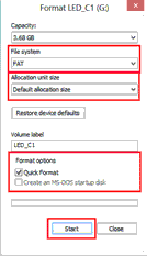 |
| Format window |
Program File placement
The program file placement inside the SD card depends on the controller usage.
| T-1000AC controller program file placement |
Unlike T-1000S controller T-1000AC doesn't support controller networking .so every controller must have a individual SD card or each controller flash should have individual programs for that controller , The file placement for each controller SD card would be like this - first two digits stands for program number (00 to 16) ,Since we use single SD card for each controller The last digit is always "1" .
Synchronization
Unlike T-1000S controller the networking capability is not available for this controller .So if you are planing to use multiple controllers together you have to use separate SD cards for each controller or you have to upload separate set of programs into each controllers internal memory .So How to synchronize the patterns , Only way is to power up all the controllers together so that every controller stats around the same time .
Troubleshooting T-1000AC Controller
This is may due to few reasons -
*. Controller cant detect the SD card - Damaged SD card,Unsupported SD card ,Unsupported file format.
fix - Check whether the SD cad is supported type (128,256,512,1GB,2GB SD card) ,Insert it to the card reader and format it using the windows format tool as I mentioned previously in this tutorial .replace the files again and try again .
*. Oxidized card pins or controller pins - remove the card and check the gold plating of the pins if they where damaged and gold plate was gone replace the card .If the controller port is damaged got gold plate was gone you have to replace the port .
*. Unknown file type or no file - The file type should be ".led" other file types may cause error light to flash.please recheck the files using a PC .
*. Different controller Type selection - If you have selected T-1000B-XXXX instead of T-1000-XXXX it will cause an error .
If you are using internal flash memory -
*. The flash memory is empty or copying files from SD card to flash memory failed .
*. damaged flash memory Chip .
No error Display but no LED effect either
This is due to physical error - Damage wires in the LED String or Damaged or oxidized port or connectors or due to selecting wrong drive chip type in the new project window check the "Selecting the Controller in the Software " section at the top of this article. If ports are damaged then you have to re solder them .If connectors are oxidized you have to use NC-Tinner to clean them you can use a used tooth brush and dip it in NC Tinner and brush the oxidized parts of the controller and the LED String or use a contact cleaner spay .
Warnings
Hot swapping - Never ever Pullout / Remove the SD card from the controller while the power is on (This will damage your SD card permanently or if you are lucky you can getaway with only file lost /Damage) .Always power off the controller wait for a second and remove the card .
Never ever reverse the polarity .Reverse polarity protection may or may not in your controller or LED String .If there is no protection it will damage the controller and Pixel LED Driver I.C .Use a multi-meter to check the polarity of the power supply output before wiring .
Since there are thousands of different manufacturers , Wire colors may change with the manufacturer .Please contact the seller or the manufacturer before wiring ,If not may cause damage to the Driver chip .
Check the Feedback of the sellers before buying online .There are many fake or damaged controllers , Pixel LED strings are available on the internet .(Be aware of scammers )
limit the amount of time you insert and remove the SD card to the controller , Because every time you doing this will cause the gold plated pins to scratch which will lead to oxidizing of the pins .
Environmental conditions may cause damage to your led string and the LED controller ,The controllers are not designed for out-door use, It's for indoor use only .If you are putting the LED string out-door please make sure to use the water sealed LED strings. But even the water sealed led strings may damage due to hash environmental conditions .



2 comments:
Thank you !
wel tutorial
Post a Comment