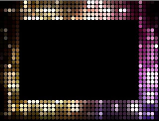
 |
| Frame Shaped LED Layout |
Before looking in to this article please visit my first LED Edit article
[Click Here].
[Click Here to Download latest LED Edit Software ]
In this tutorial I'm going to discuss how to use LED Edit software's manual layout creator option to create a representation of the actual led layout for your LED programming needs. I have discussed the use of LED Edit's Automatic layout creator to create a panel like led layouts .Most of the cases it's fine, but some times we have to design led displays in irregular shapes. In this tutorial I'm going to discuss how to use LED Edit's Manual layout Creator to design irregular shaped layouts .This tutorial is for "LED Edit" versions not for "LED Edit -K" software versions .I will add tutorials for that software versions in future .
Next Article -
[Click Here To See - How to create LED Text layouts in LED Edit Software]
I will discuss how to design some irregular shaped layouts.First of all you need to create a new project .Please follow the section of "Starting a New LED Edit Project " in my previous tutorial
[Click Here].
Creating Frame Shaped LED Layout
01 Click on "Project Config" in the top menu bar and select "Start Manual Layout" .This will bring up the manual layout designing window .
 |
| Manual layout settings window |
02 Click on "File" and select "New" .Type the size of the worksheet you want( Width and Height of the work space) .This doesn't means the amount of leds you about to use .This simply means the Size of the work space .you can choose any size but it shouldn't be less than the amount of LED's you about to use .use work space between 3x to 6x times larger than the amount of LEDs you about to use .First of all create a layout plan in a paper or in MS paint .Here is my plan
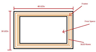 |
| LED layout plan |
03 The method I'm about to use is The BMP method .Yes , you can manually lay LEDs one by one ,but its a waste of time.To make things easy I'm going to use Adobe Photoshop Software .Run your Photoshop software and click on "File" and choose "New". If you don't have Photoshop software please download and install .
 |
| Photoshop New file window |
04 In the "New file" window Give the width and height text fields the amount of LED's in the width and height sides of your plan, in my case it's 40 LED's in width side and 30 LEDs in height side .So I give 40 and 30 (W,H) as in the image .left the other settings as above image shown and click "OK".
 |
| Zoom to fit to screen |
 |
| Enable Ruler |
05 Click on the "Zoom Tool" in the tool bar and zoom the sheet as you like by clicking in the sheet or click on "Fit Screen" button .click on "View" in the top main bar and select "Rules" to enable the ruler .
06 Click on "Edit" choose "preferences" and choose "Units and Rulers" .and select Pixels for both "Rulers" and "Type" from the drop down menu and click "OK" .Now your ruler will display in pixels .Consider one Pixel as One LED .
 |
| Ruler guide placement |
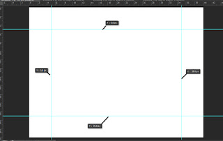
07 Now lets make our frame .Before creating the frame I'm going to create Ruler guides to make it easy to create the frame . Right click and hold on Vertical side ruler and grab it towards the sheet util it reaches 5 Pixels mark in Horizontal ruler and release the mouse .if you accidentally leave it on a wrong place ,Click on that ruler guide and hold your mouse button and drag it to the right position .
Why I choose 5 pixels ? .Because I have 5 rows of LEDs , remember 1px = 1 LED .
 |
| Ruler guide placement |
Using the same method I'm gonna place other guides as well .Look at the above photo .
 |
| Choosing the background color |
 |
| Sheet background |
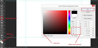
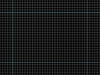
08 Now click on "paint bucket" tool from the tool bar and click on the color and choose black color and click "OK" . Now click on the sheet to make it black .
 |
| Selecting rectangle Tool |
 |
| Selecting rectangle The color |
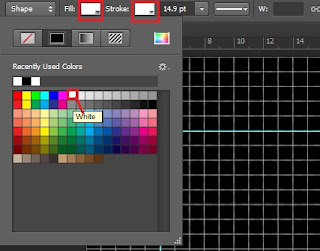
09 Now select the "Rectangle Tool" from the tool bar and in the top right you will see labels like "Fill" and "Stroke" click the rectangle in front of them and choose white color from the palette for both "Fill" and "Stroke" .Click and hold mouse button on any corner of the inner rectangle that created by the ruler guides and grab it toward opposite corner and release it (If you place it wrongly resize it ) to create the inner rectangle. Here how it's look like .
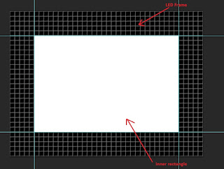 |
BMP LED layout
|
 |
| Photoshop Save As window |
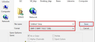
10 Click on "File" and select "Save As" .In the save as menu give any file name as file name and select "BMP" from the Type drop down list .and click on Save .
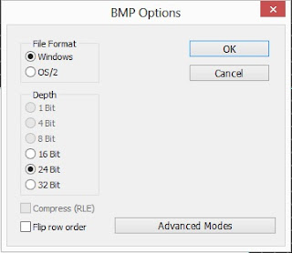 |
| BMP settings window |
This will bring the "BMP settings" window .Keep the settings as above and click "OK" .Close the Photoshop software .If it asked do you want to save ?, Choose "OK" and select a path to save the project file.
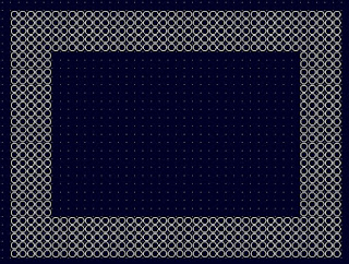
11 Now go back to your LED Edit's manual layout creator window and click on "File" and choose "Import BMP" then click "OK" and choose the BMP file that we just created and click "OK" .Place the layout anywhere in the work space .It will be something like this
 |
| BMP layout |
 |
| Line Tool |
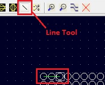
12 Now all we have to do is make the connections .you can manually do the connection by using the line tool or we can use "Auto LX " tool to Automatically do the connection . Click on "Auto LX " tool icon in the top bar and choose the method you want to wire the LEDs .I'm going to use "Left Into" and click on "Close" .
13 Right click and hold and grab the mouse cursor and release it so that the selection cover up your whole layout .
Result -
Of cause This is a not a good way to do the wiring .It's a waste of wires .I'm going to reduce the wire usage by dividing the layout in to 4 sections and use "Auto LX" tool to wire each section separately and connecting each section using line tool .Here is my plan.
Auto LX Tool
 |
| Wiring Plan |
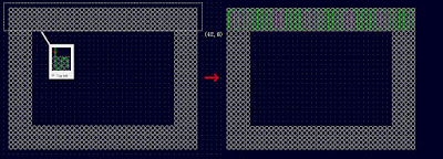
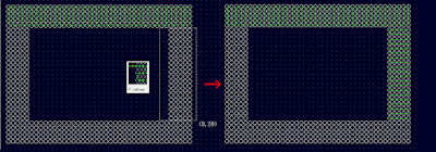
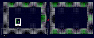
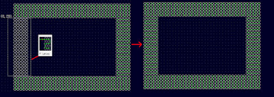
13.1 Use The "Auto LX" tool separately on each section - Click on "Auto LX" tool and choose the way you want to wire and select each section separately one by one like this -
 |
| Section 01 wiring |
 |
| Section 02 wiring |
 |
| Section 03 wiring |
 |
| Section 04 wiring |
If you wants to delete a connection click on "Quick remove connection" tool then select the section you wants to delete by click and hold while dragging the mouse pointer covering the area that contains the connections you wants to delete .
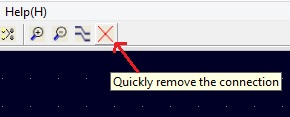 |
| Quick remove connection Tool |
Note that I had selected different wiring patterns for each section in order to lay the wires in a way so that each sections wire end's will be next to other sections wire in. Making it easy to wire and saving lot of wires .
 |
| Line Tool |
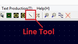
14 Now we have to connect each section in a series .Click on "Line Tool" in the top bar and connect 1st section end with 2nd sections in ,connect 2nd sections end with 3rd sections in and 3rd sections end with 4th sections in by clicking on one LED and then click on the other LED to make the connection . Don't make connection between 4th and 1st section .
 |
| Port Tool |
Connecting to the Port
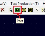
15 Now we are done with making connection between sections .It's time to connect our layout to the Port .Different controllers have different amount of ports and those port's have different amount of maximum allowed LEDs .In my previous tutorial I selected T1000-B controller and it have 1 port and that port can be connected to total of 2048 LEDs . To connect our Layout to the port (In my case port 1) we must create our port .Click on port Icon on the top bar and click beside your layout to create the port .If you need to change the port number of created port just double click on it and change it.
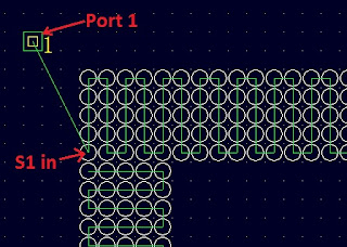
Now click on "Line Tool" and connect the port with section 1's input line by click in port and then the 1st led of section 1.
 |
| Connecting Port to layout |
16 Now we are done creating our layout .Click on "File" and select "Save" choose a path and give a name to the file and click "OK".
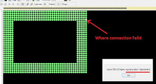
17 Now close the "Manual Layout creator" window and go back to the LED Edit main window.Click on "Project Config" and choose "Import (.cxb) " and Browse and choose the file we just created and click "OK" .If you get message like "Import ___ LED lights , Importing Failed 0 lights " . you have success fully crated and imported your layout .But if the failed lights are greater than 0 you have bad connections .
 |
| Failed connection |
Fixing the bad connections
The failed connection locations can be easily located by the white LED which means there is a error in the connection in that location .To fix this go back to "Manual layout Creator" by clicking on "Project Config" in the top menu bar and select "Start Manual Layout" . In the Manual layout creator window click on "File" and choose "Open" browse and select the file we created and click on "OK".
This will open our layout .Zoom in to the locations where connections failed and reconnect them using the "Line tool" (It will be easy if you delete the connection in that area using Quick remove connection" tool as in step 13.1 ,And reconnect them using "Line" tool).After remaking the connections save the file again this time Click on "File" and choose "save" to save on the same file .Follow the step 17 again .
 |
| No Error |
Go to my previous tutorial from (
[Click Here] and continue from the subsection titled "Recording a Video or an Animation" to apply a video or an animation to our layout .
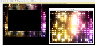 |
| Frame Shaped LED Layout |
Related Links -
Related Articles




5 comments:
Hi Sir. My name is AbdeAli from India. Your posts have really helped me a lot to learn led edit. I have started programing T-1000s controllers and it has helped me start a business. So THANKS a lot Sir.
Sir now please show us a way by which we can protect our programs from being copied from sd-cards as the common re-salers are copying and selling my work.
Sir please help.
Hello,
Congratulations for your blog and your channel You tube. Your articles and your links of downloads allowed me to develop my knowledge in modules leds pixels and the programming. I acquired 2000 leds ws2811 and the controller T -8000 ACC a short time ago, they will serve me at the back of the stage at our next choral concert. I am tenor in a choir in France and also passionate about lighting. I have two questions that you may be able to answer. I'm using Led Edit 2014 for my SWF effects. I would have liked to make programs with Led Edit 2018 but when I tried on my T-8000 it does not recognize the program recorded on my SD card, do you know why? On the other hand I would like to create notes of music to scroll on my curtain of 40 LED channels and use this time Led Easy, according to you what is the most convenient way to create these notes? Sorry I was long, thank you in advance. Cordially. Eric
Please send me your Email address so we can continue the conversation !
My Email - learnitstepbystepblog@gmail.com
Please send me your Email address so we can continue the conversation !
My Email - learnitstepbystepblog@gmail.com
sir i want to make somthing in led so i need your help can you help me sir
Post a Comment