Part - 3
Before looking in to this article please visit my first LED Edit article
[Click Here].
If you are using LED Edit-K versions please visit my first LED Edit -K article (
[Click Here])
We talked about how to use auto layout creator to create panel like layouts and we talked about how to use manual layout creator to create non regular layouts in both Led Edit and Led Edit-K versions.In this tutorial we are going to discuss how to use AutoCAD software to design any kind of led layout that you want and wire them outside the Led Edit software .Please download and install Auto Cad 2007 or higher version before continuing.I will explain how to do this in both LED Edit and LED Edit-K versions.
As I said before please install the AutoCAD software, In this article I'm going to use Autocad 2007 version but you can use a newer version .
Designing the LED layout
The Plan
In this tutorial I'm going to design a circle shaped led layout as an example but you can design any shape you like ,Before any thing ,We need a plan for our design ,Here is what I came up with .
 |
| LED layout plan |
The Led lines are equality spaced and each LED line contents series of LEDs that are also equity spaced.If you are drilling the board for led placement please consider leaving enough space for drilling holes when you placing LEDs in the lines .Board outline represents the edge of the panel .
Dimensions
The dimensions we use in AutoCAD doesn't represent the dimension on the actual physical product ,Consider this as a scaled model of that actual product designed for the purpose of simulation during programming the LEDs. Make your own dimensions for your led layout .It shouldn't be too large or too small .
OK ,Enough talking lets get started. Run your AutoCAD software .
 |
| AutoCAD work space mode selection menu |
01 Select AutoCAD classic from the work space menu ( The term "AutoCAD classic" may changed with newer versions ) and click OK. Click on "Format" in the top bar and select "Units" .In the Drawing units window select "inches" from the "insertion scale" drop down list and click "OK".
 |
| AutoCAD Drawing units window |
Creating the LED References
 |
| Circle tool |
02 Select the "Circle Tool" from tool box and click on anywhere in the work space that you wish to place the center of that circle and move your mouse cursor off that center and left click if you are satisfied with the size of the circle .
 |
| Creating a circle |
03 Double click on the circumference of the circle which will show you the properties of the circle change the geometry settings as below -
Center X = 0
Center Y = 0
Center Z = 0
Diameter = 1
 |
| Circle Properties |
 |
| Array tool |
04 Now we have created our first LED reference ,I want to create a line of LED references along the (-) X Axis .If the circle is not selected select it .Click on "Array Tool" from the right side modify menu .In the Array menu check "rectangular array" and change the settings as below image .and Click "OK" .
 |
| Array settings |
Rows - The amount of rows along Y axis .(In my case it's one because I want a line . )
Columns - Number of columns along X axis .(In my case its 15 because I want 15 of them along X)
Row offset - Offset along Y axis or distance between each rows ( In my case it's 1.0000 because I don't have any rows )
Column offset - Offset along X axis or distance between each column .(In my case it's , minus is to change the direction and 4.0000 is the distance between each led reference centers .)
Angle - The angle of the array .( In my case it's Zero )
Here is the result .15 LED references along -X axis .
 |
| Array of LED references |
Creating The Circle
05 Click on the second circle and select the "Array" tool from the modify bar in the left side, In the "Array" settings check the "Polar Array" radio button and change the setting as below .And Click "OK" .
 |
| Polar Array settings |
Center Point - X and Y coordination of the center of the objects to be copied around (In my case it's zero in x axis and zero in y axis)
Total Number of Items - Number of copies per Angle fill value .(In this case it's 15 ) you can change it to a value you prefer ,More items mean less space between items and may overlap .less items means less details .
Angle to Fill - The angle that items should be distributed (In my case its 360 because I want the items to be distributed around a full circle )
Here is the result -
 |
| Polar Array result |
06 Now we have to do the same thing to remaining LED references .Select one by one and follow the above step (05th Step ) and In polar array settings make sure center point X and Y values are zero and the Angle to fill is 360 .All you have to change is the "Total Number of Items" text field because as we go forward towards left the circle becomes bigger and bigger which means the space between items become bigger and bigger .So we have to increase the "Total Number of Items " as we going forward . You can choose a value you like .After changing the settings instead of clicking "OK" Click on "preview" button .This will show you what will be the result of your settings change . If you are happy with the result Click on "Accept" .If you are not satisfied with the results click on "Modify" and change the "Total Number of Items" value as you prefer .Try to maintain equal distance between each LED reference throughout the design .
 |
| Array preview |
Here is what is looks like after doing it to all the 15 LED references (The number in the red is the Total Number of Items per each circle) .
 |
| Final result |
Wiring the LEDs
Now we are done creating our LED layout design .Now it's time to wire them together in series .Here is my wiring plan .
 |
| LED Wiring plan |
In order to make the connecting easy we need to change the snap settings Select the line tool from the tool bar ,You will see some buttons will appear in the bottom ,Enable and disable the features by clicking on these buttons as in the image below .
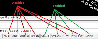 |
| Line tool features |
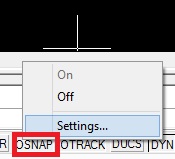 |
| OSNAP |
Right click on "OSNAP" button and select "Settings" and change the settings as below image and click "OK" .
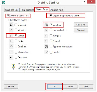 |
| OSNAP Settings window |
07 Click on "Line" Tool from the tool bar and click on the center of the first LED to be connected and then the center of the second LED then the third then the fourth etc ... Until the last LED . Note that LEDs are connected in series .After making the last connection press "Enter" button of your keyboard to exit the tool .
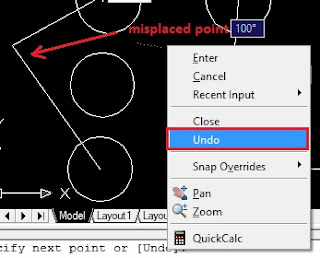 |
| Misplaced point recover |
If you mistakenly click on somewhere else instead of the center of the circle .Don't worry just right click and choose "Undo" from the drop down list and continue connecting .
Discontinuing the line - You don't have to connect every LED reference at once if you are tired just press "Enter" of your keyboard to end the line any place and at the next time select the line tool and make sure that you continue from the last place you end the line by clicking center of the last circle that you wired .
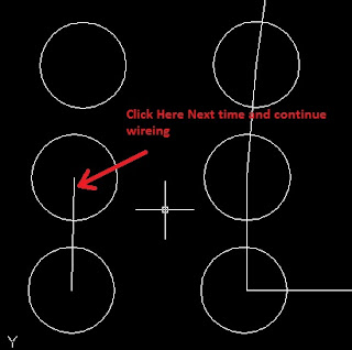 |
| Discontinuing the connection |
Here is the result after wiring the LED references .
 |
| Result after wiring |
09 Now we have to connect it to a port label.The amount of LED references in this example is 856 and it is below the number of maximum amount of LEDs that can be connected to the port of my controller (My controller can have 2048 LEDs per port ) so I can connect this led layout to a single port of my controller without any issue .But if you exceed the maximum amount of LEDs that can be connected to your controller you have to connect the renaming LEDs to another port label but you must consider the amount of ports that your controller have. Please refer to your controller user manual for details .
 |
| Text tool |
10 Select the "Multi line Text Tool" from the tool bar and click on the black space next to the first LED reference and press "0" of your key board and press "," then press "0" again finally press "Enter" .Change the size of the font to 1 inches by typing "1" in the text size field .Now type "p1" as the text (which means port 1) and click on "OK" .
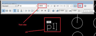 |
| Port 1 label |
Now we have to connect the port label to the LED layout .Click on the "Line Tool" in the Tool bar and click on the First LED reference center and then click on the text labels connecting point and press "Enter " .
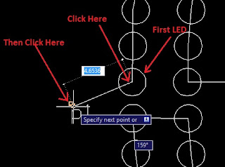 |
| Connecting the port to the LED layout |
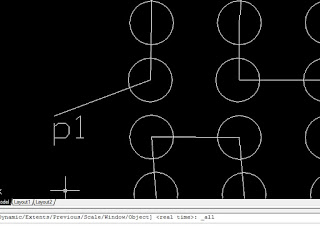 |
| Result of the connection |
If you have to use more than one port create labels representing each port and connect it to the each LED reference set like this - "p" = Port and number after latter "p" represents port number it gets connected to .
 |
| Multi port layout labels |
Final result of the layout -
 |
| Final LED layout |
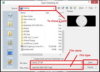
11 Now we have created our layout and connected it to the port label .Go to "File" and select "Save As " from the drop down list .In the "Save As " window select the path that you wants to save the file and give it a name by typing in the "File Name" text field and choose " and select "AutoCAD 2007 DXF (*.dxf)" from the "files of type" drop down list and click on "Save" .
 |
| AutoCAD save as window |
12 Close the AutoCAD software and run the LED Edit or LED Edit -K software .
Continue from Here >>
Importing To LED Software
If you are using LED Edit -K versions -
12.1 Click on "File" and select "New" to create a new project and select your controller and click "OK" .(
[please click Here for more information on project creation] ) and refer to the "Starting a New LED Edit Project " section of that tutorial .
 |
| Import dxf |
12.2 Click the "Import dxf" icon from the left side panel. Browse and select the file that you have created and click "OK" .You will see the dxf file settings menu select the settings as bellow image .Use scaling slider to change the scale of the importing file and click "OK".
 |
| dxf file settings |
You will see a message showing how many LED reference that have imported successfully .
 |
| Import successful message |
If there are connection fails ,you will get a message like this .
 |
| Import failed message |
If you get a message like above click "OK" and notepad will pop up which will show the locations that connections failed .
 |
| Note pad - failed connection locations |
Close it and zoom the LED layout using your mouse wheel and you will see the failed connection references in violet color and successfully connected led references in yellow color with blue lines connecting them .
 |
| Connection failed location -Zoomed |
Note that locations and go to and reopen the dxf file in AutoCAD by double clicking the file .Go to the locations that your connections are failed by using the mouse wheel (Zoom in / Zoom out) and select the current connections around that location by clicking them and erase them by right clicking and selecting "Erase" and remake the connections by selecting the line tool from the tool bar and click in the centers of the circles .Press enter to exit the line tool .Do this to every connection failed location and press "Ctrl" + "S" to and save the file (Follow step 11 and 12). Go and continue from the 12.1 step again .
 |
| remaking failed connections |
 |
| Successfully imported layout |
12.3 Import the dxf file successfully without errors and start programming the layout
[CLICK HERE to program the layout]Please refer and continue from the sub section titled the "Recording a Video or an Animation " in my First LED Edit - K lesson .
 |
| Programming the layout |
If you are using LED Edit versions -
13.1 Click on "File" and select "New" to create a new project and select your controller and click "OK" .Please refer to the "Starting a New LED Edit Project" section of my first LED Edit tutorial for more information on creating a new project
( Click Here ).
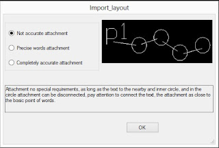
13.2 Click on "Project Config" in the top bar and choose "Import (.dxf)" .This menu will appear ,Check "Not accurate attachment" and click "OK" . Open file window will appear , Browse and select the file that you have created and click "OK" .
 |
| Import dxf file settings |
13.3 if you successfully imported the file ,You will see a message like this .stating that importing failed are zero .Click "OK" .
 |
| Import successful message |
13.4 If you get message like this . which states that failed lights are greater than zero ..
 |
| Import failed message |
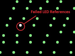
13.5 Click "OK" and zoom the layout using your mouse wheel and look for LED references that are white colored which means that connections failed on that location .
 |
| Failed LED references |
Note that locations and go to and reopen the dxf file in AutoCAD by double clicking the file .Go to the locations that your connections are failed by using the mouse wheel (Zoom in / Zoom out) and select the current connections around that location by clicking them and erase them by right clicking and selecting "Erase" and remake the connections by selecting the line tool from the tool bar and click in the centers of the circles .Press enter to exit the line tool .Do this to every connection failed location and press "Ctrl" + "S" to and save the file (Follow step 11 and 12). Go and continue from the 13.1 step .
 |
| remaking failed connections |
Import the dxf file successfully without errors and start programming the layout ( please refer and continue from the sub section titled "Recording a Video or an Animation " in my LED Edit Tutorial





15 comments:
hello there is someone for a question?
super I followed your tutorial but at the time of the opening in lededit 2019 and but all the led in one point I do not understand why
please explain more ...
I do the desin with autocad 2007 like you when I finished, I record it as you. And when I open the dxf in lededit 2019 all LEDs are grouped in 1 LED
That's due to bad connections .please make sure the connecting lines snapped to the center of the LED reference.
If that doesn't fix your problem ,Please use older version of LED Edit software .
here is my email deamon@sfr.fr if you could send me an email disappointed so that I send you a screenshot
I did ! . Thank you for your comment !
The same thing happens to me, please help
Also have this problem. All pixels in one place. Led edit 2019.
The same problem. Connections snapped to the center. All pixels on one pace. Tested with LedEdit 2019-K, 2018-K, 2017-K
Please. help
O.P (Morgan) found a solution for this .Please change the system language to English !
Hello again! I've tried to change the system language to english (united states) and it didn't work. Maybe I'm loosing something in the way? Using Autocad 2020 saving as 2007's dxf and LedEdit-K 2019 4.6. I really need this for a job project, if you could help me out would be awesome! Reply me if further details are needed. Thanks in advance, have a great day!
@Leonardo Drews Montibeller , please use Autocad 2007 version .Saving as 2007 dxf file in Autocad 2020 will not work !
Send me an Email - learnitstepbystepblog@gmail.com
I will send you some test dxf files !
Hey, I've finally solved the problem! It's because of the OS language version. Must be an english Windows version. So I've installed Windows XP English in one virtual machine and it finally worked! Thanks! Excellent blog!
Post a Comment