Watch The Video Tutorial
Custom Pixel LED Layout
Custom pixel LED layouts are pixel LED arrangements that not square or rectangular in shape. Which means the layouts that cannot be created or very hard to design within LEDEdit software. The most convenient way to create such layout is by using a third party software to create and import it to LEDEdit software. This gives the user the freedom to design the layout without a limitation. Here are some of our previous articles on custom pixel LED layouts.
How to create custom pixel LED layouts in LEDEdit software.
How to create custom pixel LED layout in AutoCAD software.
How to create custom pixel LED layout with CorelDRAW and AUTOCAD.
The Layout Plan
The
first step is to create a plan for your layout . The plan can be a
drawing in a piece of paper or computer generated image of your actual
layout. This is the plan of the physical product . There are certain
data that should be included in such plan. Here are some of them. But ,
you can include anything that helps you to make things easy .
Basic components should be included in the plan -
| Custom pixel LED Layout Plan |
• Pixel LED placement positions.
• Guidelines.
• Amount of pixel for each components of the layout.
• Distance between each separate component of the layout. (Approximately)
• Dimension of each component. (Approximately)
• Amount of LEDs for each component.
Custom Pixel LED Layouts with CorelDRAW
For
this tutorial we will design a custom text LED layout using CorelDRAW
software. Since, We are designing the text layout using CorelDRAW .There
is no limitation to your design . You can illustrate anything you like
.You can custom design your font too. Here are the basic requirements
for this tutorial .
Requirements -
• CorelDRAW X4 or X5 version . (LEDEdit cannot read the connection data of layouts created using later versions of CorelDRAW)
• LEDEdit 2014 or later version.
Creating a New Project
• Double click on the CorelDRAW icon and launch the software.
• Click on "Blank Document" in the quick start menu or Click on "File" and select "New" .
 |
| CorelDRAW New project |
• In the "Create Project window" . Type a name for the project in the "Name:" field .
• Choose the measurement unit by clicking on the drop down menu next to the width input field.we are going to leave other settings as they are (Default) and click on "OK".
Creating the Guide lines
The first thing we need to do in CorelDraw is to create set of guide lines for our text layout . Guidelines can be useful when it comes to placing each component (In this case character) in the layout . It helps you to set some parameters such as size and distance between each character . So you can easily and quickly setup your layout. Guidelines will not appear on the final product .Here are some of the things that you need to consider when creating guidelines.
• To create guidelines you need to enable the Ruler . Click on "View" and check "Rulers" by clicking on it.(If its already checked leave it)
• The next thing you need to do is to enable the guidelines . Click on "View" and check "Guidelines" by clicking on it. (If its already checked leave it)
 |
| CorelDRAW ruler settings |
• To change the Ruler settings , Click on "Tools" and select "Options". In the options window .Click on the plus sign next to "Document" and expand it.Then ,Click on "Rulers".
• Setting The origin - In default coordinates of the top left corner is 0.0 in horizontal axis but not 0.0 on vertical axis . This can be little confusing when taking measurements . Lets set it to zero in each axis . In the origin section type the Height of the document in the "Vertical" input field (to get the height of the document go to File >> Document Properties. You can see it next to "Document Size:" (Width x Height) ) .
• After changing the settings click on "OK".
Creating Outer Guidelines
 |
| Text outer guidelines |
• Click on "View" and check "Rulers" by clicking on it.(If its already checked leave it) .
•
First of all we needs to select the guide layer . Look at your right
side menu there will be a "Object Manager" tab click on it (If you cant
see the object manager go to Windows > Dockers and check "Object
Manager").
 |
| Selecting Guide layer |
• There will be a label called "Guides" click on it. To
create a vertical guideline click and hold left mouse button on the
horizontal ruler and drag your mouse to the area that you want to place
the guideline and release the button.
 |
| Creating Guidelines |
• To create a Horizontal guideline click and hold left mouse button on the vertical ruler and drag your mouse to the area that you want to place the guideline and release the mouse button.
• Note: To make guideline placement easy you can make it snap to the ruler nudges by checking View > Snap to Grid .
Creating Text Guide
The first step is to create a text guide so we can use it in the future placement of text. In this tutorial we will create a text that contains the word "LED EDIT" . Lets say , for a sign board .You need to select a font for your text design .We are going to use "Bauhaus 93" as the font. Here is how to create the guide text.
•
Make sure you are in the guides layer .( In the right side menu there
will be a "Object Manager" tab click on it.There will be a label called
"Guides" click on it.)
• Click on the "Text tool " in the left tool box or press F8 button of your keyboard.
• Click on anywhere in the workspace and type whatever you like.
• Right click on the text that you have created and select "Character Formatting" .
 |
| Character Formatting |
• In the character formatting menu (appeared on the left panel) select the preferred font from the font drop down menu .Type the font size in the font size input (You can change it later). Click on font alignment and choose a font alignment that you like. Choose a font effect from "Font effect" drop down list.
 |
| CorelDraw Scaling the text |
Once you done that . Click on the text and move the cursor towards any corner of the text selection until you get the scale cursor . Then press shift key of your keyboard and click and hold the left mouse button while dragging it toward the area that you wants it to be scaled .Do it until it fit inside the outer guidelines.
• To move the text move your cursor in top of the text until your cursor becomes move icon .Then , Click and hold your left mouse button while dragging it to the place that you want it to be.After you reach the position , leave the left mouse button to place it.
Creating LED Placement Guides Curves
Right
click on the text and select "Convert to Curves" and again right click
on that text line and select "Break Curve Apart" .Then , Press "ESC"
button of your keyboard to deselect .Now you can click on each separate
character of the text.
Text outer Guides -
• We need to take one character at a time and create the outer guides. Lets take the first letter "L" . Lets break apart the letter "L" . We are going to break it on the corners. To do that we need to select these corners .
 |
| CorelDraw Shape tool |
•
Click on the shape tool from the left toll bar and click on the four
corners of the letter L while "Shift" key pressed. Then , Right click
and select "Break Curve apart" .
 |
| Selecting The corners |
 |
| Break Curve apart |
• Click on the Pick tool from the toolbox and right click on the letter "L" then select "Break Curve Apart" . Press "ESC" of your keyboard to deselect .
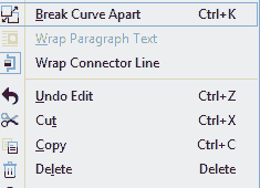 |
| Break Curve Apart |
Text Inner Guides
As you seen in my plan .We have 3 pixel LED lines inside the letter "L" .So , we need three guides inside the character "L" .
• Now you can select each section of the letter "L" separately. It's time to create the inner guides using these outer curves (Guides) . Select the outer curve that best represent inner shape of the letter.
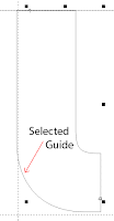 |
| Selected outer guide curve |
Select the section of outer guide curve that near represent the inner shape .Then , Press "Ctrl" and "C" to copy.
• Make sure you are in the guides layer .( In the right side menu there will be a "Object Manager" tab click on it.There will be a label called "Guides" click on it.)
• Then , Press "Ctrl" and "V" to paste. The element will pasted in top of the original guide curve .
 |
| Scaling the guides |
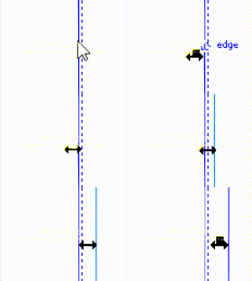 |
| Scaling guide curves |
• Scale the pasted guide curve to the position that you need inside the character.
 |
| Text guide curves |
• Repeat above 4 steps to all the inside led placement guides.
 |
| re-shaping the curve |
Here is how its look like when all the Inner guidelines were completed.
| pixel led placement guides |
Creating Led placement Guides
Now we have created our guide curves , It's time to create pixel LED placement guides along these curves. Lets take the first character ("L") . We have two inner guide curves and four outer guide curves .But , Placement of the inner guideline curves will coverup two outer guide curves (Horizontal top curve and vertical bottom curve) . So , We don't need to place guides along these curves. Lets create the guides along the left side outer guide curve.
 |
| Creating Ellipse |
• Click
on the "Ellipse" tool from the tool bar and left click on the worksheet
while holding "Ctrl" and "Shift" of your keyboard. Drag you mouse away
from the clicked point . Leave the mouse when you reach the size of the
ellipse that you wants ( the size of the ellipse should be equal or
greater that 1.0 unit ) . Press "Esc" to deselect.
 |
| Resizing Ellipse |
• Click on the Ellipse using the pick tool and change the size (Enter the with and height) using the top property bar (Both width and height should be equal . It should be equal or greater than 1.0 unit).
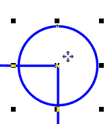 |
| Moving Ellipse |
• Using the pick tool move the ellipse to the end (any End) of the curve that you about to place the guides along .
• Select the Ellipse and press "Ctrl" and "C" of your keyboard to copy it .
• Make sure you are in the guides layer .( In the right
side menu there will be a "Object Manager" tab click on it. There will be a label called "Guides" click on it.)
• Then , Press "Ctrl" and "V" to paste. The Ellipse will paste in top of the copied Ellipse .
| placing pixel led guides in curve ends |
• Use the pick tool (In the left Tool bar) select the ellipse from the center and move the pasted Ellipse to the other end of the guide curve (you will see the cursor text become "node" as the ellipse is at the end of the curve).
• Go to windows > Dockers and check "Blend" by clicking on it (If already checked leave it ).
• Select one Ellipse and select the other (at the other end) while pressing "Shift" Key in your keyboard .
 |
| Blend Settings |
• In the right side panel (Blend Settings tab) type the amount of LED guides you need along the guide curve in the input field. Then , Click on "Apply" .
 |
| Blend along the curve |
| Pixel LED guide placement along Curve |
• Do this to other guide curves in the letter . Here is the result . (Make sure you are doing everything in the guide layer).
| Pixel LED placement Guides |
Do the same to other characters as well . Here how its looks like when every character is done .
Grouping Guides
To make things easier or to make things clear you can group the guide elements of a character .So that it's easy to use in the future .
 |
| Grouping a single guide letter |
• Click on pick tool in the left tools menu . Then ,click near the character that you wants to group and hold left mouse button while dragging the cursor covering the character area . Leave the mouse button .
 |
| Selecting the Guide layer |
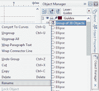
• Make sure you are in the guides layer .( In the right side menu there will be a "Object Manager" tab click on it.There will be a label called "Guides" click on it.)
 |
| Renaming The Group |
Duplicating Guides
| Renaming pixel LED guides |
• Once the completed character is placed over the non-completed character . Select the non-completed character from the object manager and press "Delete" button of your keyboard to delete it.
Follow above steps mentioned under "Creating LED Placement Guides Curves" and "Creating Led placement Guides" to complete the other letter guides . Here is what it's look like after all the guides been completed.
 |
| Select and move layers |
•
Click on "Object manager" tab in the right side menu. Click on the
pencil icon in front of Guide Layer .(the Icon will cross out) .This
will prevent you from accidentally editing the things on guide layer .
If you wants to edit guide layer afterwards , re-click on the pencil
icon.
• Go to "View" select and check "Snap to Objects"
 |
• Once you done that click on the center of the ellipse and hold your mouse button , Drag it on top of any pixel LED placement guides and leave your mouse button (As the cursor text will become"Center")
| Copy and move pixel LED references |
Wiring pixel LED Reference Points
• Click on bottom right corner of "Free Hand" tool in the left toll bar. A side menu will appear . Select "Pen" tool .
| Individual Character Wiring |
Grouping pixel LED References
• Make sure you are in the layer that contains the LED references that you wants to group (Right side menu "Object Manager" Tab )
• Click on "Arrange" and select "Group" . To rename the group click on the grouped LED references and go to object manager (In the right side panel ) . You can see the selected group is highlighted .Right click on it and select "Rename" .Then type any name you like . Press Enter .
Duplicating Pixel LED References
• Group the character and the wiring as we have mentioned in the above section. Rename it as you wish.
• Click on the completed and grouped reference character and press "Ctrl" and "C" to copy it.
• Make sure you are in the Layer that you wants to paste it . (Right side menu "Object Manager") .
•Press "Ctrl" and "V" to paste it . (will be pasted over the original ).
 |
| Moving grouped reference points |
After all the pixel LED reference points have been placed and Guides layer hidden .Here is how its look like.
| pixel LED reference points |
Wiring Between Characters
Now we have done wiring each individual characters . It's time to wire the them together . Each character that connect to a specific port should be connected in series . In this tutorial we are going to use single port for single line of text . Hence , two ports needed . In this case the text line "LED" connected to port 1 and text line "EDIT" connected to port 2 . So , Lets connect the first line of text .• Click on pen tool from the tool box .
 |
| Wiring between letters |
• Then we are going connect the letters in the second line same way . Press "Enter" after connecting last two letters of that line . Now , All the characters have been connected , here how its looks like .
• Since , We are connecting the two text lines to separate ports , There is no connection between them .
• As we did the wiring in such way so that the wiring end of previous letter is right next to the wiring start of the next letter .
Creating a Port
• Click on the text tool ( In left side tool box) and click near the first character of the first text line ("L") . Then , Type "p1" without any space (p1 means Port 1 ) .
• For the next line we are going to do the same . But , we are going to type "p2" instead of "p1" ( p2 means Port 2 ) .
• You can type any port number you wish to connect the pixel LED references to . Type "p" followed by port number .
Connecting to Port
 |
| Connecting the Port |
• Using pen tool click on the first reference point's center (cursor text will display "node") of the first letter then move the pen tool on top of the port label that we have created in the above section (In this case "p1" ) . move the cursor near the left of the text . The cursor text will become "text baseline" click on that point .
• Create and connect any other port labels to corresponding pixel LED references . Here how it's looks like after connecting port 1 and port 2 to two text lines .
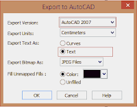
• In the export window browse the location that you wants to export the layout file to . Type the file name in the "File Name : " text field .
• Click on the "Save as File Type" drop down menu and select "DXF-AutoCAD (*.dxf) " . Then , Click on "Export" .
 |
| Export settings |
Importing The Custom LED Layout
LEDEdit Versions -
• Create a new project . (please refer to our basics lessons if you don't know how to LEDEdit Basics )
• Click on "Project Config (C)" and select "Import (CorelDraw .Dxf).
• A window will appear check "Not accurate attachment". Click "OK".
• Browse and select the file location .Then select the file and click on "Open"
• If everything went OK . You will see a message like this .Stating the amount of pixels that have been successfully imported. Click "OK" .
 |
| Successfully imported dxf layout file |
LEDEdit-K Versions -
• Create a new project (please refer to our basics lessons if you don't know how to LEDEdit -K Basics).
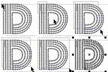
• Click on "Edit Layout" .
 |
| LEDEdit dxf import settings |







8 comments:
why when importing dxf file, it says sometimes , reduce the canvas of the led layout
Can you explain further ?
when I imoprt DXF file it says unable to read the layout about lights
What LEDEdit version , Coreldraw Version you are using ?
Greetings. Thanks for the detailed manual.
But I got a problem while importing dxf. When importing, all points have the same coordinate, what could be the reason?
CorelDraw 2020, LedEdit-K V8.0
Sorry CorelDraw 2020 dxf files are not supported by LEDEdit software . You need CorelDraw X3 , X4 or X5 versions.
Yes, CorelDraw X3 helped me)
Hi,
Can I import an DXF file on 2021 version of led player?
Post a Comment